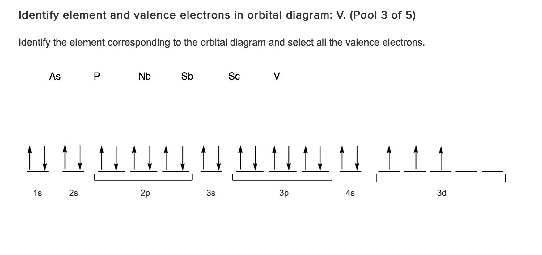

Here, the outermost shell contains 1 electron that is 2S¹.įor Be, the configuration is 1S² 2S², and the number of valence electrons is 2. Valence electrons are electrons present in the outermost shell or highest occupied principal energy level and can be found out easily by the electronic configuration of an element.įor example, Li has a 1S² 2S¹ configuration. When valence electrons are arranged around an atomic symbol, then it is called an electron dot diagram or Lewis dot structure. In this lesson, we will discuss the electron dot structure of C (Carbon) and other elements. Yes, with the help of electron dot diagrams. The question is, how are different compounds formed? Is there an easy way to analyze how many bonds are going to be formed of an element with another one?
#ANTIMONY ELECTRON DOT DIAGRAM HOW TO#
Read more about how to correctly acknowledge RSC content.Oxygen forms H2O, carbon forms CH4, while boron forms BH3. Please go to the Copyright Clearance Center request page. In a third-party publication (excluding your thesis/dissertation for which permission is not required) If you want to reproduce the whole article If you are the author of this article, you do not need to request permission to reproduce figuresĪnd diagrams provided correct acknowledgement is given. Provided correct acknowledgement is given. If you are an author contributing to an RSC publication, you do not need to request permission To request permission to reproduce material from this article, please go to the CV studies of 6 suggested its potential application as a reducing agent, which was further proved via the conversion of Tip–PCl 2 to trimeric (Tip) 3P 3 ( 17), and cAAC P–Cl (cAAC = cyclic alkyl(amino)carbene) to (cAAC) 2P 2 ( 18) and 4, utilizing 6 as a stoichiometric reducing agent.įluorescent organo-antimony compounds as precursors for syntheses of redox-active trimeric and dimeric alkali metal antimonides: an insight into electron transfer reduction processesĮ. The existence of 1˙ − was proved using electron paramagnetic resonance (EPR) spectroscopy in solution. 5 undergoes oligomerization in the solid state to produce 6. Cyclic voltammetry (CV) studies of 1 in THF showed possible two electron reduction, suggesting the in situ generation of the corresponding radical-anion intermediate 1˙ − and its subsequent conversion to the monomeric intermediate (Tip) 2Sb − ( 5) upon further reduction. All the reported compounds have been characterized via NMR, UV-vis, mass spectrometry, and single-crystal X-ray diffraction analysis. Interestingly, the precursors 1 and 4 have been observed to be highly luminescent, emitting green light under short-wavelength UV radiation. The Lewis acidic character of 19 has been unambiguously proved via treatment with Lewis bases to produce the corresponding adducts 20 and 21. Additional reactivity studies involving 1 and AgNTf 2 (Tf = trifluoromethanesulfonyl) afforded the corresponding antimony cation (Tip) 2Sb +NTf 2 − ( 19). In this report, different aspects of the various reducing agents ] used have been studied, correlating the experimental observations with previous reports. Changing the reducing agent from KC 8 to a different alkali metal resulted in the solid-state isolation of corresponding stable dimeric alkali metal antimonides with the general formula (M = Li ( 14), Na ( 15), Cs ( 16)).

The two-electron reduction of 1 and 4 afforded the novel trinuclear antimonide cluster ( 6). (Tip) 2SbCl ( 1, Tip = 2,4,6-triisopropylphenyl) has been utilized as a precursor for the synthesis of the distibane (Tip) 4Sb 2 ( 4) via one-electron reduction using KC 8.


 0 kommentar(er)
